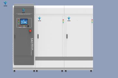
The Sodium Hypochlorite Generator produced by electrolysis method adopts the method of diaphragm free electrolysis.
Effective chlorine production: 50-600000g/H
Effective chlorine concentration: 3-10g/L
Installed power: 0.3-90KW
Host size: Customized delivery cycle: 7-25 days
WhatsApp: +86 19953182842
Email henry@hoclshine.com
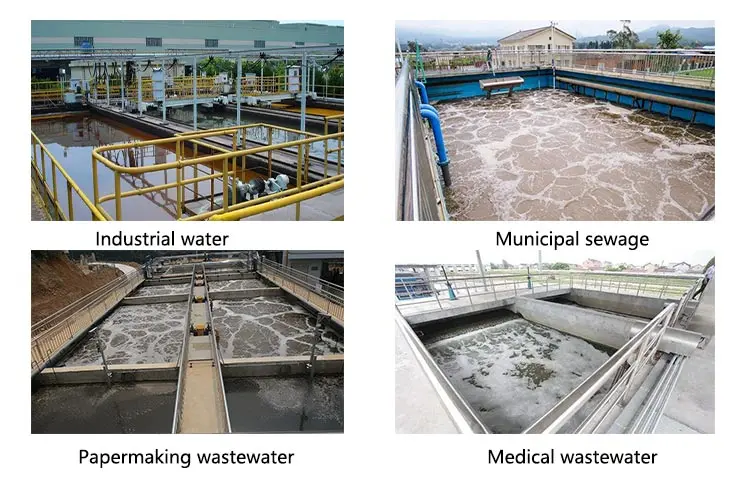
The advantage of the electrolytic Sodium Hypochlorite Generator is that it can generate sodium hypochlorite as needed without storing or transporting hazardous hypochlorite. This plays an important role in water treatment, sanitation, and industrial applications.


| Effective chlorine production | 50-60000g/h |
| Effective chlorine concentration | 3-10g/L |
| Installed power | 0.3-90KW |
| Host size: Customized delivery cycle | 7-25 days |
| +86 19953182842 | |
| henry@hoclshine.com |
The electrolytic sodium hypochlorite generator uses electrolysis technology to decompose sodium chloride ions (NaCl) in saltwater into chloride ions (Cl -), hydrogen ions (H+), and sodium oxide ions (Na+). At the anode, chloride ions are oxidized into free chlorine atoms, generating chlorine gas (Cl2); At the cathode, water is reduced to hydrogen gas (H2) and hydroxide ions (OH -). At the same time, hydrogen ions combine with hydroxide ions to form water molecules (H2O), releasing a large amount of heat during this process.
NaCl+H2O → Na++Cl -+H++OH-
2Cl - → Cl2+2e - (anodic reaction)
2H++2e - → H2 (cathodic reaction)
When the concentration of chloride ions in saline water increases, the generated chlorine gas also increases accordingly, while the production of hydrogen gas is not affected by the concentration of chloride ions. Therefore, the concentration of sodium hypochlorite solution can be adjusted by controlling the current and time in the electrolytic cell.


Submitted successfully
We will contact you as soon as possible